Recovery
Do not SKIP!
WARNING
This process is not supported by the manufacturer or supplier of your Gateway.
DISCLAIMER
In some cases there is no way of knowing your exact situation and taking the wrong actions could make things worse, potentially leading to a bricked Gateway. Anyone following this guide accepts full responsibility for the outcome(s).
Recovering gateways on optimal bank plan
If you followed rooting guides from this Wiki, you were suggested to implement the so called optimal bank plan.
This recovery method is not available if...
- You are not or no more on optimal bank plan
- Your
/overlay/bank_1contents is messed up - Your active bank is
bank_2 - There are no RBI firmware images of
Type 2available for your board
Recovery from any bad state (excluding full overlay partition issues) while optimal bank plan is in place, always consists in following this path:
- Use BOOTP flashing to flash a valid
Type 2firmware for your board. Because of optimal bank plan, the Gateway is guaranteed to boot this sort of recovery disk frombank_1. TheType 2image you choose to pick now for recovery purposes does not depend on which one you have inbank_2. If this is not your first time booting this recovery disk, choose the sameType 2firmware you used in past. - Being on optimal bank plan your
/overlay/bank_1is assumed to be in a good shape as whatever you work on daily is inside/overlay/bank_2instead. For that reason the gateway will boot just fine the image you just flashed. Fire up your SSH client and get in the root shell. If this is your first time booting this recovery disk you will need to hack it following Type 2 rooting instructions stopping just after Final Type 2 steps. - Whatever was wrong and causing issues with your mods related to the firmware you were booting from
bank_2is now inside/overlay/bank_2folder. Fix it manually if you know what was your mistake, otherwise restore/overlay/bank_2folder contents from a previous overlay backup. If you didn't get any (shame on you) forget about whatever you were running frombank_2, jump to Bank Planning and go on to the end like you probably did the first time you read that page. Do not come back to this recovery guide. - When you have finished, go back booting form
bank_2: runmtd erase bank_1to eject this recovery image and reboot.
DO NOT...
- Do not switch active bank, it always has to be
bank_1 - Do not apply any mod except root access while booting the recovery disk
- Do not try RTFD or bootfail
What if my overlay partition is full?
Optimal bank plan is not intended to make things easier in such cases. You can still try booting recovery as explained above and wipe the filled up partition as soon as you get a root shell. Expect something in the above step 2 to go wrong: either your recovery disk doesn't boot fine (bootloops) since something running upon startup is crashing because of file writing failures, or you can't get root access because root strategies fail to apply needed changes. Your chances to sort out from this situation are bigger if this is not the first time booting into recovery since everything usually created upon startup and root access is there already.
Wipe Custom Data Partition
Technicolor Gateway platforms are usually built on a firmware + data design, which consists of read-only filesystems (squashfs) stored in flash banks plus a writable filesystem (jffs2) for user dafa storage.
In modern Homeware firmware's, based on a fork of OpenWrt (Chaos Calmer 15.05), the user data partition is an overlay, it's contents get applied on top of the root filesystem, which is stored as read-only firmware in the booted bank. For dual-bank gateways, the user data partition contains a differing overlay for each firmware bank.
The space available in the the user data partition is shared across both bank's overlay's.
If you think you are not completely aware of what's going on or you don't know what you did wrong, it is strongly recommended you just completely wipe the user data partition only as follows, which will wipe all custom config.
This reset method is not available if...
- You have lost any kind of access to root shell by either SSH, Telnet, or Serial console, and you cannot execute a custom command as root.
- The Gateway bootloops or fails to boot properly.
- The Gateway uses the ubifs filesystem on the
rootfs_data/userfspartition.
- Log in to root shell (whatever you have available to you; SSH, telnet, serial console ...)
- Run
cat /proc/mtdand look for your user data partition name, it could be eitheruserfson older devices, orrootfs_dataon newer ones - Run
mtd -r erase rootfs_dataormtd -r erase userfsaccordingly.
Reset to Factory Defaults (RTFD)
If at some point you can no longer connect to the Gateway or you want to make a fresh install, it may be useful to perform a Reset to Factory Defaults (RTFD).
Note
A RTFD deletes all changes you made to files and configurations on the booted bank. After the reset, a reconfiguration and a reroot of your Gateway will be needed.
This feature is implemented by an official tool from Technicolor you can invoke in different ways. Choose between:
- RTFD via the web interface
- RTFD via the reset button
- RTFD via the CLI (shell)
Unroot prevention may break RTFD
Procedures and guidelines found in this wiki won't break ordinary RTFD functionality. However, some heavy mods, like the custom tch-nginx-gui, also install modded RTFD scripts to prevent loosing root access on RTFD, and this means RTFD may also fail. These scripts are also designed to survive after RTFD. This means you might be unable to get rid of them by doing RTFD. If the Gateway had one of these mods installed and RTFD does not work for you, then check the mod details. You might need to repeat RTFD twice or do a full data partition wipe.
RTFD via the web interface
This RTFD method is not available if...
- The web interface is corrupt and not accessible.
- The Gateway bootloops or fails to boot properly.
- The
userfsorrootfs_datajffs2 filesystem is full.
- Browse to the Gateway web interface.
- Click Gateway. The Gateway page appears.
- Click Reset.
- The Gateway deletes all customized data for the booted bank and restarts.
RTFD via the Reset Button
This RTFD method is not available if...
- The physical reset button of the Gateway have been disabled.
- The Gateway bootloops or fails to boot properly.
- The
userfsorrootfs_datajffs2 filesystem is full.
- Make sure the Gateway is turned on and completely booted.
- Push the Reset button for at least 7 seconds and then release it.
- The Gateway will delete all customized data for the booted bank. You will need to reroot.
RTFD via the CLI shell
This RTFD method is not available if...
- You have no access to the CLI by either SSH, or Telnet, or serial console.
- The Gateway bootloops or fails to boot properly.
- The
userfsorrootfs_datajffs2 filesystem is full.
- Make sure the Gateway is turned on and completely booted.
- Login to the CLI (RTFD is also available in restricted shell if needed).
- Run
rtfd - The Gateway will delete all customized data for the booted bank. You will need to reroot.
Manually do what RTFD does
This reset method is not available if...
- You have no access to the root shell by either SSH, or Telnet, or serial console.
- The Gateway bootloops or fails to boot properly.
- The
userfsorrootfs_datajffs2 filesystem is full.
- Make sure the Gateway is turned on and completely booted.
- Login to root shell.
- Run
rm -rf /overlay/bank_N- Where N is either number of the bank you want to RTFD.
- Turn off device to reboot. You will need to reroot.
Restore your settings
If you previously backed up your configuration, you can now restore it to your Gateway.
BOOTP flashing
This guide is useful if you need to load a different firmware on your bank_1 firmware partition, in case of a downgrade or replace a corrupt one.
Your firmware is unlikely to be corrupt!
If your Gateway stopped working normally after some mods or tweaks, it is very unlikely you messed up the firmware partitions since all your mods and settings are stored in the userfs or rootfs_data partition instead. Reloading a firmware in such situations won't make any difference unless you load a different version which is known to somehow work fine enough with your messed up mods & settings.
This should work for any known Technicolor device build on a Broadcom BCM63xx platform. Since basically forever, Technicolor gateways have had a corrupt firmware recovery mechanism built in.
By holding down a button (usually reset) at power on, the Gateway will enter BOOTP mode which will allow you to flash firmware into bank_1, while the appropriate software is running on your PC
If both firmware banks contain invalid firmware's, the Gateway will enter BOOTP mode automatically after three failed boot attempts on both banks.
Please note and take into account
-
Unless your device is a CobraXh, this will not automatically switch the active bank for you, if the active bank is
bank_2and it still contains a valid firmware it will still boot it, instead of the one you are flashing here. The CobraXh will only enter BOOTP if the active bank isbank_2, and it will automatically switch tobank_1after successful firmware flash. -
Unless your device is a CobraXh, flashing via this method does not perform any factory reset, the new firmware will run on old and possibly corrupt or incompatible config. It is therefore recommended that you perform a factory reset before flashing a new firmware. The CobraXh, on the other hand, will perform a factory reset on both banks after successful firmware flash.
-
The firmware BLI image (.bli/.rbi files) is digitally signed, and the signature is verified by BOOTP before flashing, so you can't flash an incorrect image (a good thing) but you also can't load a modified image (sad face times 1000).
Set up TFTP
This guide is written for Windows but it should work on Linux too if you adapt the configuration.
What you will Need
-
A computer running a DHCP server and TFTP server.
This guide uses TFTP64 for windows which implements both. -
RBI firmware file for your specific Gateway board.
-
A wired ethernet connection with static IP address assigned.
BOOTP recovery mode does not support Wi-Fi. -
A few cups of coffee
-
About 30min to an hour
Setting up the Server
-
Download the latest normal edition of TFTP64 and install it.
-
Get the firmware file you want to load into the Gateway from the Repository and place it in the TFTP64 folder. You may use another folder and change the settings appropriately if you wish.
-
Connect the Ethernet port on your PC to one of the LAN ports on the Gateway (usually LAN1).
-
Turn the Gateway off.
-
On the PC ensure the network card you wish to use is set to DHCP
- Press Windows+R to run
ipconfig /all | find "DHCP Enabled"or check multiple cards withipconfig /all. Microsoft help page. (Unless you are using Static IPs on your network this will already be done. After the next few steps, the network card will receive an address from the TFTPD64 DHCP server.)
- Press Windows+R to run
-
Start TFTP64.
-
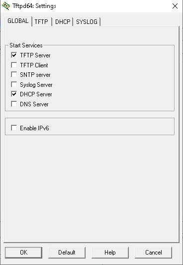
Click Settings.
-
On the GLOBAL tab enable only the following: TFTP Server, DHCP Server.
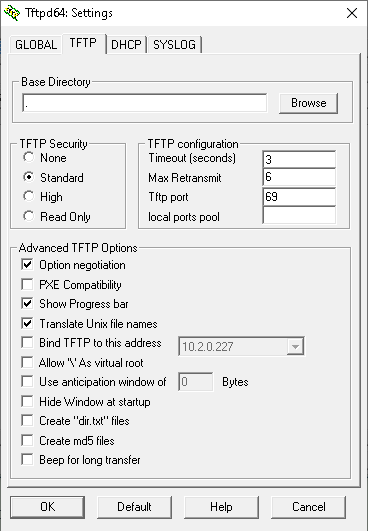
-
On the TFTP tab the default options should be OK (base directory should be
.)
-
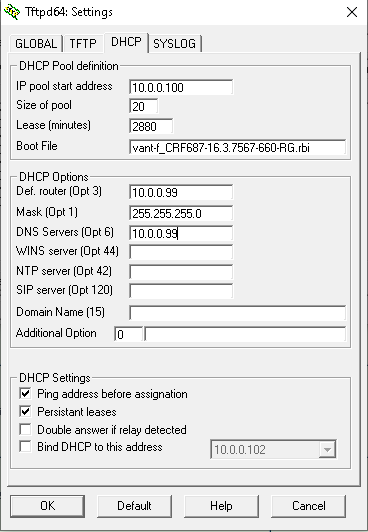
On the DHCP Server tab:
-
IP pool start address:
10.0.0.100 -
Size of pool:
20 -
Boot file: the firmware filename to flash i.e.
vant-f_CRF687-16.3.7567-660-RG.rbi -
Def. Router (Opt 3):
10.0.0.99 -
Mask (Opt 1):
255.255.255.0
-
-
Click OK
-
Click Accept when prompted to restart.
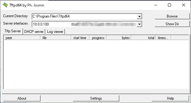
-
On the main screen Change the Server Interfaces selection to your Ethernet network card.
-
Close TFTPD64.
-
Re-open TFTPD64.
-
If you get a firewall warning, allow access on both private and public networks. Please note the temporary network between your PC and device in BOOTP mode will always be of public type by default.
- If you don't get any firewall warning and you don't remember if you have already allowed access for TFTP64 in past, please, check firewall settings to confirm it's allowed already or temporally disable firewall.
The server interface should now show an IP in the 10.0.0.x range and after a few seconds, the PC gets an IP from the TFTP64 program via DHCP.
You are now ready to try booting the Gateway to do the flash!
Flashing the Firmware
-
Set up TFTP to send firmware in BOOTP mode as described above or in this guide.
-
Ensure TFTP is on the log viewer tab.
-
Connect one end of the network cable to any LAN port on the Gateway, DO NOT use the WAN port, and the other end to the nic on the pc.
-
Place Gateway into BOOTP mode, this is achieved by turning it off, holding the reset button down and powering on.
- For TG789vac and TG799vac wait for the ethernet light to flash.
- For TG800vac count to about 5.
- For CobraXh wait for the power light to flash white.
- TFTP may detect the sooner though.
-
Let the firmware flash, a download progress bar will show. When completed, the Gateway will start flashing the received firmware. Wait for the Gateway to reboot.
- It may take a few attempts for TFTP to connect and send the firmware, and you may have to put the Gateway into BOOTP mode again if you send no firmware's for a while.
-
After Gateway has rebooted, wait for approx 4-10min.
From here, Gateway has the firmware you flashed into its bank_1 partition.
A few things to note
-
Again, the Gateway will not boot from this new firmware if
bank_2is active and contains a valid firmware (unless your device is a CobraXh). -
If you followed rooting guide on this wiki and your bank plan is still optimal you are guaranteed to see this just flashed firmware to boot because active bank is always
bank_1on optimal bank plan. -
TFTP does not always play nice and may require a few loads to get working, as well as mentioned above, BOOTP mode can be a pain.
-
This guide and process will not work if your device is bricked at bootloader stage.
-
If you did not perform RTFD for
bank_1before TFTP flashing and the new firmware is not fully compatible with previous one, you may now have booted into an unstable setup. This might also cause the webui of booted firmware to show a misleading firmware version number obtained from past firmwares leftovers. If so, you either need to perform RTFD now or wipe user data partition. Read above sections.
This concludes the BOOTP flashing process. Depending on what you are trying to achieve by flashing a firmware via BOOTP, you might now go back to guides which brought you here.
Check booted bank
Dual-banks gateways work very similar to a dual-boot computer system. For example, the computer might have a data partition with personal data and two OS partitions, each with a different OS. The gateway has a data partition and two firmware banks.
When you power on your device it starts loading by default the firmware from the so-called active bank. With no surprise, the other one gets called passive bank. Of course only one bank at time can be used.
BOOTP flashing via TFTP writes into bank_1 only
BOOTP flashing allows flashing a valid firmware into bank_1 only and will do so even if the active bank is currently bank_2. It will never set bank_1 as active.
In order to check which firmware bank is currently set as active bank" you can do any of the following:
- Read contents of
/proc/banktable/activefile or run thebootmgr partition activecommand if that file does not exist. This requires you have root access to the gateway. - Read serial console log during boot. This requires a serial adapter connected to the gateway device board. Recommended in case of soft-bricks.
- Flash some different, yet valid firmware from BOOTP via TFTP and see if the flashed firmware is being booted by default. This is recommended whenever you have yet to root the gateway for the first time and it is in normal working order.
Change booted bank
Whenever the Gateway fails to load the firmware image three times in a row from the active bank, the bootloader will enter Bootfail mode and will try booting from the inactive/passive bank, without setting it as active. If the firmware inside passive bank fails too, then the bootloader will automatically enter BOOTP flashing mode for firmware recovery.
The process of switching the active bank is called switchover, and does not involve flashing or upgrading firmware. Which one is your current active bank depends on how many times your device did a switchover, So it's best to understand when this is usually occurring.
Switchover usually occurs on every regular firmware upgrade done via sysupgrade. Regular firmware upgrades get installed to the passive bank, and a switchover occurs at the end of the upgrade process if it was successful. This means your Gateway frequently changes active bank while not unlocked.
To force-boot from the other bank, which by definition is not currently active, you have two options:
- Set it as active (switchover), and let the gateway boot it regularly
- Trigger a Bootfail, and let the gateway fallback to the passive one
Switchover
If you have shell access to the Gateway, or you can easily get root or run arbitrary commands from your firmware version, this is easy as you only need to run the switchover command, or manually update contents of /proc/banktable/active with either bank_1 or bank_2. For example this will set bank_1 as active:
echo bank_1 > /proc/banktable/active
If you have no shell access, but you have the possibility to run a firmware upgrade (for example via web interface, AutoFlashGUI or CWMP), as previously stated, a switchover will be executed automatically at the end of the process. Get an RBI firmware for your board from the Repository, prefer to use the same firmware version you're currently running for this purpose, or pick a newer one if any, no matter the Type. Downgrades are likely to be disallowed. Please note: this will also imply a firmware flashing via sysupgrade and every drawbacks it derives.
If none of the above options are viable in your situation, unfortunately you must opt for Bootfail instead.
Bootfail Procedure
Bootfail comes handy whenever you have no root access to your Gateway and you want to forcefully boot the passive bank for any reason.
The most common case where you can use this trick is if you have a Gateway that you have just flashed a new firmware via BOOTP into bank_1, but your active bank is currently set to bank_2, where you have a firmware you can't easily root, so you won't be able to boot your new firmware.
Another common case is that your gateway has self-updated to a firmware version you can't easily root. For example, a new Telstra Frontier Gateway that has unfortunately updated to v17.2.0261-820-RA can be reverted to the firmware in the passive bank (usually 16.3) using this method. This makes the rooting process a breeze!
Key Point: Once you get your passive bank booted, it sadly won't be marked as the active one for the next boot, therefore you will need to repeat the following steps every time you would like to boot that bank until you take appropriate actions.
Which kind of actions?
If you came here starting from this wiki index, just keep your device powered on and continue reading, the rooting guide, which includes the correct bank setup steps. Otherwise, cast your eyes over to the switchover section.
Here you find some alternative ways of triggering a Bootfail. The chance of success is very high if you read the bootlogs from the serial console while performing the procedure.
SysRq reboot
This is so far the easiest and more comfortable way of forcing bootfail, but you are required to connect the gateway serial console to input the reboot command. Read further for other bootfail methods where serial console is not strictly required.
You can read the SysRq commands theory and their magic keys from Wikipedia. In short, you connect the serial console, wait for "Starting the Linux kernel" message to appear and immediately press Ctrl+Break followed by b+Enter on your keyboard. This would cause the kernel to fail and trigger the next boot attempt. Repeat this thrice in a row and you will see it finally try booting from the inactive bank.
Timed reset button action
This method tries force a bootfail through the hardware reset button. The technique tries to cause an abnormal reset process by depressing the reset button in a non-conventional or unexpected manner.
Hardware reset normally requires the reset button to be depressed for a period of time and then released, after which the modem is left to go through its reset process. The bootfail technique tries to cause a failure by subsequently depressing the reset button in a particular sequence, which could consist of multiple presses of varying time periods. This bootfail technique is dependent on the hardware implementation of the modem and is independent of the firmware that may be installed. As a result, different model modems are likely to require different sequences to cause a bootfail. Once a bootfail technique is discovered the technique is replicated two more times so that three successive bootfails occur, which triggers the bank switch.
The following provides two examples of different model modems:
DJN2130 Telstra Frontier Gateway
This is the button pressing sequence for the DJN2130 Telstra Frontier Gateway with v17.2.0261-820-RA loaded.
The sequence is (Minutes:Seconds):
| Step | Period | Time | Action |
|---|---|---|---|
| 0 | 0 | 0 | Power on |
| 1 | 00:35 | 00:35 | Press reset |
| 2 | 00:11 | 00:46 | Release |
| 3 | 00:47 | 01:33 | Press reset |
| 4 | 00:11 | 01:44 | Release |
| 5 | 00:47 | 02:31 | Press reset |
| 6 | 00:11 | 02:42 | Release |
| 7 | 00:50 | 03:32 | Press reset |
| 8 | 00:11 | 03:43 | Release |
| 9 | 06:00 | - | Browse to 192.168.0.1 and confirm firmware version |
DJA0231 Telstra Smart Modem Gen 2
This is the button pressing sequence for the DJA0231 Telstra Smart Modem Gen2. It has proven successful with various firmwares including 20.3.c.0432-MR21.1-RA which is not vulnerable to tch-exploit.
- Start with normal factory reset process using the reset button.
- Watch the front light which should soon become bright white.
- When the front white light dims:
- Hold the reset button for 10sec.
- Release and hold the reset button back down for another 10sec.
- Keep repeating step 3.ii above until the front light becomes bright white again at which point release the reset button completely.
- Keep watching the front white light. When it dims again repeat all of step 3 (second time).
- Keep watching the front white light. When it dims again repeat all of step 3 (third/last time).
- Leave modem to fully boot.
This method is shown in this video.
Crazy Power switching
If you power on your device, and rapidly toggle power switch on and off fast enough it won't get the required power to remain on,
the bootloader will fail to load and pass firmware validation and corruption checks. Once such checks fail, device will reboot for a new boot attempt. Repeat such that the first three boot attempts fail, then let the fourth attempt to complete.
This method is perfectly described in this video.
Potentiometer
This works the same as the above Crazy Power Switching, but uses some hardware to precisely control the power. You will need:
- A 3 watt and 100 Ohm Potentiometer
You only use the middle and outside poles and you split the positive cable to the middle pole from the power supply then the outside right pole looking down at the 3 poles from the knob side to the plug going to the Gateway.
Once powered on around 10-15 seconds into the boot cycle you want to turn it around 1/3 turn and just a little more and wait for the led to flash blue then turn it back up and do this 3 times then it will boot on other bank.
CNC DC DC Buck Boost Regulated Power Supply
This is similar to the Potentiometer approach above, but it is easy to monitor progress just by watching the current display on the power supply. When it hits the current limit the PSU momentarily switches to CC mode, the voltage drops and the boot fails, shown by the current reverting to 0.29A as the cycle starts again.
As with other bootfail methods, you count 3 fails and then allow it to boot normally – in this case by raising the settings to 12V, 2+A.

(Source: Whirlpool)
Automatic monitoring of serial console
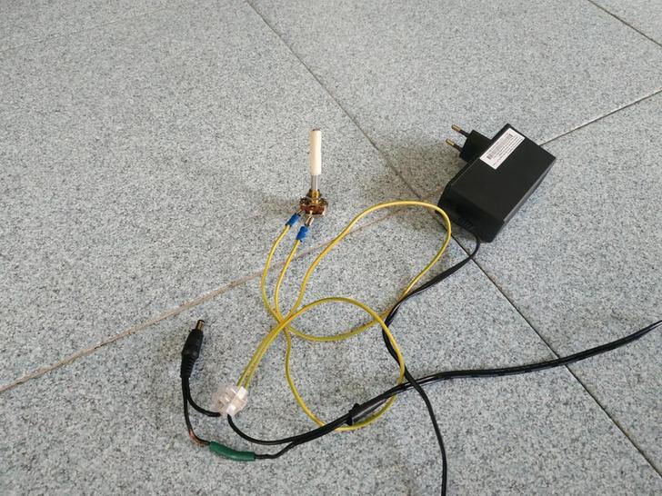
A Python program written by Mark Smith is available on GitHub that you can run on a Raspberry Pi which monitors the serial console output from the Gateway and then automatically cycles the power to the Gateway to cause a brown-out condition during boot, to reliably force a temporary bank switch.
Please see the pictures for the physical setup, and the comments at the top of bouncer.py for more technical details (it may require timing tweaks for different models).
If you do any electronics and have some relays and transistors lying around, you probably already have everything required for this!
NAND glitching
This is a last resort if you can't manage to get any previous working. There are high chances that NAND flash will get damaged. By temporary shorting specific NAND pins you can cause NAND CRC error which will force the bootloader to fail and retry booting. After 3 times glitching the NAND this way bootfail is triggered. It is difficult to do this in the exact moment when the firmware is loading, thus connecting to the serial console is highly recommended.
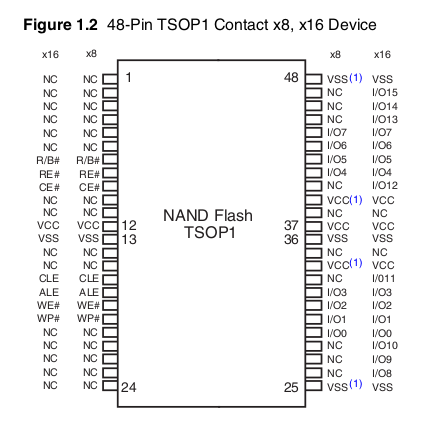
You need to short VCC (12) and VSS (13) pins as soon as you see a message Starting the Linux kernel. Put a needle or similar object between VCC and VSS for an instant, you should hear a small sparkle to fire, take the needle away as soon as it happens. A few moments later, the bootloader shows an error. This will repeat 3 times in a row and you should finally see a message Booting : Bank 2 (bank 1 failed 3 times).
An example serial console log:
Decompressing Bootloader................................
Gateway initialization sequence started
Boot Loader Version : 2.0.67
CPU                 : BCM63169-D0
RAM                 : 256MB
Flash               : 128MB NAND, blocksize=128KB, pagesize=2048B
Board Mnemonic      : GANT-1
Market ID           : FFFCExternal switch id = 53125

Booting             : Bank 1
nand: ECC uncorrectable!
nand: ECC uncorrectable!

Unhandled TLB

Unhandled exception (core 0):
EPC=0x81321244, BadVAddr=0xc24fe000, RA=81321594

Call stack:
    8131fd0c 81320008 81319da8 8131a0d0 8130deb8 81332d90
    ...
    8131a224 8131a0d0 81320edc

Exception frame:
812ff4d0: 10 00 04 03 00 80 00 08 81 32 12 44 c2 4f e0 00    .........2.D.O..
...
812ff5f0: 81 34 a0 00 81 2f f6 48                            .4.../.H

...

Decompressing Bootloader................................
Gateway initialization sequence started
nand: error M
nand: ECC correctable

Boot Loader Version : 2.0.67
CPU                 : BCM63169-D0
RAM                 : 256MB
Flash               : 128MB NAND, blocksize=128KB, pagesize=2048B
Board Mnemonic      : GANT-1
Market ID           : FFFCExternal switch id = 53125

Booting             : Bank 1 (attempt 2)
nand: ECC uncorrectable!

Unhandled TLB

Unhandled exception (core 0):
EPC=0x81321244, BadVAddr=0xc2220000, RA=81321594

Call stack:
    8131fd0c 81320008 81319da8 8131a0d0 8130deb8 81332d90
    ...
    8131aa10 81317178 8131f854 8131a884 8131a3f0 8131fa78

Exception frame:
812ff4b0: 10 00 04 03 00 80 00 08 81 32 12 44 c2 22 00 00    .........2.D."..
...
812ff5d0: 81 34 a0 00 81 2f f6 28                            .4.../.(

...

Decompressing Bootloader................................
Gateway initialization sequence started
nand: error M
nand: ECC correctable

Boot Loader Version : 2.0.67
CPU                 : BCM63169-D0
RAM                 : 256MB
Flash               : 128MB NAND, blocksize=128KB, pagesize=2048B
Board Mnemonic      : GANT-1
Market ID           : FFFCExternal switch id = 53125

Booting             : Bank 1 (attempt 3)
nand: ECC uncorrectable!
nand: ECC uncorrectable!
nand: error E

Unhandled TLB

Unhandled exception (core 0):
EPC=0x81321244, BadVAddr=0xc246e000, RA=81321594

Call stack:
    8131fd0c 81320008 81319da8 8131a0d0 8130deb8 81332d90
    ...
    8131a224

Exception frame:
812ff4b0: 10 00 04 03 00 80 00 08 81 32 12 44 c2 46 e0 00    .........2.D.F..
...
812ff5d0: 10 00 04 03 00 80 04 00                            ........

...

Decompressing Bootloader................................
Gateway initialization sequence started
Boot Loader Version : 2.0.67
CPU                 : BCM63169-D0
RAM                 : 256MB
Flash               : 128MB NAND, blocksize=128KB, pagesize=2048B
Board Mnemonic      : GANT-1
Market ID           : FFFCExternal switch id = 53125

Booting             : Bank 2 (bank 1 failed 3 times)
Magic packet        :
SW Version          : 0.0.0.0.0
Starting the Linux kernel

[    0.000000] Initializing cgroup subsys cpu
[    0.000000] Linux version 3.4.11-rt19 (repowrt-builder@8d48c62ce462) (gcc version 4.6.4 (OpenWrt/Linaro GCC 4.6-2013.05 r48709) ) #1 SMP PREEMPT Sat Mar 3 04:16:44 UTC 2018
[    0.000000] GANT-1 prom init
[    0.000000] CPU revision is: 0002a080 (Broadcom BMIPS4350)
...